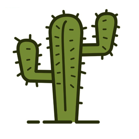
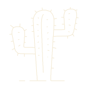
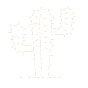
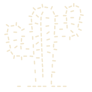
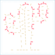
Applies to the source-linked cactus experiments in iterations 07–14. Earlier debugger snapshots have no verified image registration, so they are not overlaid. Historical experiments stay historical.
A practical starting point
Make your first sashiko stencil.
Sashiko Stencil Workshop turns an image into a stitch plan and a digital stencil for 3D printing. Work through Artwork, Mask, Stitch, Check, and Export in order.
Choose and crop your artwork
Open the workshop and choose an image or a starting shape. A clear subject with distinct lines or flat colors is easiest to review. Crop away unwanted background before continuing. Edit crop returns to the original image during this workshop session; applying a new crop resets the mask edits and generated result.
Confirm the mask
The mask selects the area you want to work with. For flat artwork, choose the relevant colors; disconnected marks of the same color can belong to one selection. Use object selection or follow drawing lines when appropriate, then brush areas in or out. Check holes and small details before accepting the selection.
Plan your stitches
Choose whether to follow the original drawing or replace its selected area with a pattern fill. Set the physical size and review the generated stitches. A fill is a new pattern inside the artwork, so it will not preserve every original line. Read any warnings about missing details or continuity.
Check the stencil
Review the actual openings, material between them, and fit on your printer. Changing the physical size can change which details survive. A geometry check evaluates the digital model; it does not prove how a particular printer, filament, or marking pen will perform.
Save, print, and test
Review the visibility and current purchase options, then download the STL and editable design when unlocked. The STL is for a slicer or printing service; the editable design lets you reopen the project. Test your print and removable marker on a scrap of the same fabric before transferring the full design. No physical stencil is shipped.
Sign-in and purchase requirements appear in the workshop. Public sharing requires permission to share your artwork. For pricing and marking-tool questions, read the download FAQ.
Open the workshopThe development log below explains how we arrived at the current approach. Historical experiments are labeled and are not all current workshop defaults.
00a · Before the spacing experiments
First, what did we detect?
Before blaming stitch placement for a missing spine, we need to see whether that spine survived image processing. This is a replay of the actual cactus input, followed by archived snapshots of the Workshop extractor before iteration 10. The later ink-fit revision is shown separately below. These are processing stages, not new historical iterations or hand-redrawn approximations.
Original imageThe preserved color pixels feed both branches.
Selection → maskWhich pixels are included? A filled area, not stitch holes.
Line detection → pathsWhere did the artist draw? Curves, branches and line weights.
Mask + paths + physical settings → stitch planThe Workshop combines these; the experiments below isolate path placement.
A1Decode and preserve the source

416 × 399 px → 448 × 448 px fixture The upload path fits large images within 2,048 pixels per side and keeps an original-color copy. This small cactus needs no downsize. The hero fixture adds white padding for a square plate; it does not stretch the cactus. Pixels are not millimeters yet.
A2Separate the plate from the artwork

Opaque input · full rectangular initial plate mask The initial plate mask uses transparency when present; otherwise it includes the whole image. Cream means included, blue means excluded in these mask views. This square is not the cactus selection or a compiled stencil. A stitch-guide plate is defined later in millimeters.
A3Make the automatic drawing selection

57,521 included pixels · brightness ≤ 128 Drawing mode deliberately uses the deterministic threshold generator: include opaque pixels whose weighted brightness is at most 128. On this image it selects the fill as well as the outlines. It has no understanding of a cactus, a spine, or the importance of a small mark.
A4Review the selection, not the stitches

58,767 included pixels · existing demo fixture In the Workshop, the user can choose regions, brush pixels in or out, inspect cleanup warnings, then confirm the mask. For reproducibility, the existing cactus demo instead uses its fixed rule: alpha above 128 and every RGB channel below 220. This is not a recorded brush edit or an AI segmentation result.

What changes for photos, brush edits and mask confirmation?
Object/photo mode tries available segmentation providers instead of forcing the drawing threshold. The configured cloud path uses foreground detection and selectable object proposals; point prompts refine selection. Failures can fall back to other providers and then basic contrast selection. None of those remote model outputs is claimed or pictured in this cactus replay.
Add/erase brushes change a copy of the binary mask. Confirmation extracts drawing features from the original colors, separately from the selected mask. The working image then goes through contrast, optional blur, brightness threshold/inversion, mask exclusion and configured line-thickness processing. A fresh cut mask is derived from that processed image. Those raster-preprocessing controls do not rerun line detection on the altered black-and-white image.
The images above stop at selection. The offline cactus experiments bypass that browser-canvas preprocessing and reuse the original-color paths. The final 123-slot experiment also checks its rectangular plate and slot clearances, not the uploaded image’s pixel mask. End-to-end validation of edited masks remains a separate requirement.
- Decision
- Keep selection and line information separate. A good silhouette alone cannot preserve the drawing’s interior marks.
- Validation
- Replayed the real threshold generator and compared it with the existing fixture: 1,246 differing pixels, explicitly exposed above.
- Tradeoff
- The current demo and Workshop do not share identical mask preparation. Mask quality is not established by a successful downstream stencil compile.
- Next question
- Is the information we care about still present when the original colors become paths?
00b · Follow the original ink
A silhouette is not the drawing.
We return to the preserved original—not the binary selection above. The following outputs are captured inside extractDrawingFeatures. Keeping them visible lets us distinguish a detection failure from a later decision to omit a perfectly well-detected mark.
B1Sample brightness at a bounded resolution

320 × 320 analysis pixels Sample the original at cell centers, with a maximum side of 320 pixels. Convert RGB to brightness using 0.2126 R + 0.7152 G + 0.0722 B. Transparent pixels and near-white values of 240 or more are ignored. The one-pixel analysis border stays empty.
B2Identify non-white support

30,286 non-white analysis pixels This temporary support includes the green fill and dark marks. It defines the brightness histogram for line detection; it is not the user’s editable selection mask. Treating this silhouette as the whole drawing would already lose the central rib and interior dashes.
B3Separate dark ink from lighter fill

Measured split: 87 / 255 · 11,849 ink pixels Choose an Otsu threshold from the non-white brightness histogram. Unlike the fixed mask threshold of 128, this split is calculated from the image. For this cactus, the dark outline and marks survive while the lighter fill is removed. A solid monochrome logo takes a boundary fallback instead; this image takes the line branch.
B4Measure ink width before thinning

Blue → cream: increasing distance inside the ink Estimate the distance from each ink pixel to its edge. Later, each path receives a median width estimate from this field, resisting unusually thick intersections. This stores evidence for regular and wide slots; it does not yet cut any holes or decide their printable width.
B5Thin strokes to their centerlines

11,849 ink pixels → 1,862 skeleton pixels Iterative Zhang–Suen thinning removes edge pixels under connectivity rules, up to 160 rounds. A thick drawn line becomes one centerline, not two outline paths. Sampling and thinning can still move a curve or lose tiny input features; fewer pixels is not itself a likeness score.
B6Trace endpoints and junctions
96 raw routes · colors distinguish neighboring routes Walk connected skeleton edges between endpoints and junctions, then trace remaining loops. Avoid redundant diagonal links when a direct pixel connection exists. The short spine branches are visible here, before any minimum stitch length is enforced.
B7Join the most continuous directions
96 raw routes → 59 joined routes At a shared junction, pair the most nearly opposite incoming directions. This follows the likely continuation of a drawn stroke; it is not a merge of neighboring stitch slots. Unpaired branches remain separate routes. Colors identify routes, not thread recommendations.
B8Smooth, simplify and retain line evidence
59 paths · 322 points · no capacity truncation Smooth interior points with a 1:2:1 average, then simplify at 0.0012 normalized tolerance. Drop paths at or below 0.004 normalized length; cap output at 256 paths and 16,000 points. Blue marks the 50 paths tagged as short detail—not a semantic count of cactus spines. The original width estimate stays attached to each path.
- Decision
- Preserve original-color centerlines and their width evidence instead of generating everything from a filled mask.
- Validation
- The real extractor produces 59 paths from this PNG, including the visible short branches. Replaying it exactly reproduces the cached source routes used by the existing experiments.
- Tradeoff
- This confirms source continuity, not perfect tracing. The 320-pixel analysis, smoothing, simplification and small-path cutoff can all affect likeness before packing starts.
- Next question
- Once those paths have real-world dimensions, can full-size slots represent them without colliding?
00c · Where image processing meets fabrication
Give the paths a physical size.
A normalized path has no printable stitch length yet. Convert it to millimeters, apply the chosen interpretation, and only then measure which marks can become slots. The two outputs below establish the input and crowded test case used later in this log—not a new production default.
C1Map, filter and place source paths
59 routes · 184 mm square · 1.10× artwork · 0° Multiply normalized coordinates by the physical width and height. At detail level 0.8, this route stage keeps short-detail paths at least 0.88 mm long; that is an input-path filter, not a printable slot minimum. This experiment then enlarges and recenters the artwork. Interior fill is off so we can measure fidelity to the actual drawing.
C2Try full-size slots, then expose conflicts
167 slots · 127 red · 130 conflicting pairs The original diagnostic planner separates sharp turns into runs, accepts source lengths from 2 mm, and proposes 5 mm slots along their tangents. Short accepted marks are extended, never printed at 2 mm. Clearance uses the entire rounded 1.5 or 1.75 mm opening and a 2 mm material gap. Red means this placement fails that gap check; the compiler rejects it.
The Workshop can also repeat a chosen pattern inside the selected area instead of following detected lines. Its planner combines the artwork mask, interpretation, line-weight setting, acceptance threshold and manual edits. These experiments deliberately compare drawing-led placement policies on identical source paths; they are not every possible Workshop interpretation in sequence.
Traceability and how to reproduce these images
Generated with node scripts/generate-image-process-examples.mjs. It calls deterministicMaskGenerator, captures optional snapshots inside shared/drawing.ts, and checks that the resulting physical paths match cactus-source-routes.json. It also verifies the crowded layout against the existing likeness experiment.
Source SHA-256: 280e3e33f2c83d545a8940f58fde62b165796a74e4358cfee698c93898e4d54a. Assets and counts are generated offline; opening this page does not run segmentation, change Workshop settings or regenerate the hero. The trace is opt-in and does not alter the extractor’s result.
- Decision
- Measure what survives at each boundary: pixels → selected area → ink → paths → full-size slots → compiled openings.
- Validation
- The reproduced crowded control has 127 red slots. The short branches exist in the source paths, so their later disappearance cannot all be blamed on mask detection.
- Tradeoff
- A detected feature is not guaranteed a slot. Tight junctions create competing claims on the same material, and resolving them can destroy the likeness.
- Next question
- The chronological iterations below explain how we changed those decisions, including the failed spine-less result and the branch-preserving candidate that replaced it.
Now the development history has a visible starting point. We know what the image-processing stage supplied; the following iterations document what we tried to do with it.
01 · Establish the product constraints
Start with the material.
A convincing stitch illustration is not automatically a printable stencil. A stencil is a connected plate with holes removed. Those holes need room between them, including their rounded ends.
- Minimum slot centerline
- 5 mm
- Regular / wide openings
- 1.5 / 1.75 mm
- Material between openings
- At least 2 mm
- Material outside the design
- 6 mm border
These are our product constraints, not universal limits for every printer. We removed print-time estimates from the experience: layer settings, speed, material and the slicer determine the actual print.
- Decision
- Make physical dimensions part of planning, not a check added after drawing the preview.
- Validation
- Measure rounded opening boundaries in millimeters. Screen zoom changes presentation, never the physical output.
- Tradeoff
- The original illustration contains marks that do not meet the new minimum length. A faithful-looking SVG can no longer stand in for a printable plan.
- Next question
- Can we recover short details without showing slots below 5 mm?
02 · Recover detail without breaking the length rule
Keeping detail created a new problem.
The first 5 mm minimum simply rejected shorter marks. It respected the length rule, but the cactus lost small details and its recognizable rhythm. We added Stitch Acceptance Extension: accept source marks as short as 2 mm and extend them to 5 mm, rather than drawing unprintably short slots.
Historical candidate set, replayed from the retained legacy data. Red means a slot is involved in a clearance conflict, not that its length is too short.
We first exposed the lost marks through 0.5 mm histogram buckets, then a continuous acceptance chart. The slider made the tradeoff visible. But extending a mark around its center also moved its ends closer to neighboring openings.
- Decision
- Let users accept detected marks down to 2 mm and extend them to 5 mm. Make the threshold and recovered marks visible.
- Validation
- 64 retained marks became 136 in the historical candidate set, but 104 now had clearance conflicts.
- Tradeoff
- Length compliance recovered the detail, but extending slot ends consumed the material between neighboring stitches.
- Next question
- Can scale, orientation or local movement create enough space for those recovered marks?
Line weights, masks and preview consistency
Source-image thickness became a separate signal: bold source lines could produce wider slots while keeping the same 5 mm minimum length. Scalloped edges were tried as a visual identifier, then removed because they made the openings look lumpy. Smooth 1.5 mm regular and 1.75 mm wide slots became the rule.
Acceptance and mask correction also had to remain distinct. Acceptance recovers detected short marks; brushing a mask restores areas detection missed. Neither operation proves the resulting openings are printable.
We found that the hero, debugger and compiled preview were not always showing the same geometry. The hero was connected to a single planned-and-compiled result, rather than separately styled stitch and stencil illustrations. This later experiments in this log remain separate from that compiled hero asset; they are not silently shipped as defaults.
03 · Search before discarding detail
Move the stitches. Measure the consequences.
We tested overall artwork scale, alternating stitch angles, whole-artwork rotation and bounded local movement. The important distinction: artwork scale spreads slot centers apart; it does not stretch the slots themselves.
Scale + artwork rotation
Expand positions and tilt the whole cactus to test corner-to-corner fit. A rigid rotation preserves pairwise gaps; it only changes the footprint.
Zigzag allowance
Rotate individual slots around their centers. This can separate aligned ends, but can also create new conflicts with nearby contours.
Local adjustment
Move small conflict neighborhoods within a bounded distance. Initially clear stitches are pinned; introducing a new conflicting pair is rejected.
Manual editing
Select, move, rotate, erase or lasso slots with undo. Manual edits remain separate from automatic search so a comparison cannot quietly overwrite them.
The original fixed-zigzag search evaluated 110,898 combinations of scale, angle, phase and artwork rotation. That was exhaustive on one finite model, not a continuous global optimum. We kept it off the main UI thread in a browser worker. WebGPU or WebAssembly alone would not fix an inadequate objective or missing contour information.
- Decision
- Test artwork placement and bounded stitch movement while holding slot length and width fixed. Keep manual edits reversible.
- Validation
- The finite grid evaluated 110,898 combinations. Rotating the whole artwork changed bed fit, not pairwise clearance; moving individual slots could create new conflicts.
- Tradeoff
- Searching more settings did not tell us which neighboring marks belonged to the same source contour, or which details mattered most.
- Next question
- Could similar conflicting slots be combined without damaging the drawing’s rhythm?
04 · Reject a misleading improvement
Fewer red marks was the wrong victory.
Early merging reduced conflict counts by lengthening replacement stitches or thinning entire runs. The score improved while the drawing got worse: the baseline broke into isolated dashes, and endpoints pulled away from the cactus trunk.
We tightened merging: preserve slot length, average a pair’s undirected angle, pin endpoints of longer runs, allow at most one removal per run and reject a pitch increase above 50%. If those constraints cannot fit, leave the conflict visible.
That fixed destructive cleanup, but it did not solve the underlying crowding. In the legacy-data workflow comparison, two orders finished at 91 red stitches with five removals. Adjusting before merging reached 87 red stitches with seven removals. Scale was 1× and zigzag was 0°, so two supposedly active stages were doing no spacing work.
- Decision
- Stop using aggressive pair deletion as the repair strategy. Constrain merging to preserve length, endpoints and rhythm.
- Validation
- Conservative legacy workflows still ended at 91 or 87 red stitches. Fewer removals protected the drawing, but did not solve its crowding.
- Tradeoff
- We accepted visible conflicts rather than hiding them by destroying the pattern. Cleanup after dashing was the wrong place to solve distribution.
- Next question
- What if we planned stitch counts and positions on the original paths before creating the slots?
05 · Change the planning model
Go back to the paths, not the dashes.
The turning point was retaining detected contour and run IDs from the original cactus. We could now count and space slots along a source path, split at substantial corners, and avoid treating nearby marks on different contours as one run.
New source-linked dataset: 167 starting candidates. This is not the historical 136-stitch dataset above, so the two baselines are not directly comparable.
Contour spacing uses the shared production slot packer. It solves the count and spacing of fixed-length slots along each run, checking their actual rounded boundaries. It does not repeatedly delete pairs until the red disappears.
Our first ordering still let short decorative marks occupy space needed by defining long contours. Reserving longer contours first raised the best result from 94 to 114 slots and reduced omitted multi-slot runs from three to zero. It traded away more short details, which we report rather than hide.
- Decision
- Keep source route/run identities and solve spacing on those paths. Reserve the longer contours before short marks.
- Validation
- The source-linked experiment reached 114 slots and zero conflicts, with every multi-slot source run represented.
- Tradeoff
- Longer-first was an assumption about importance, not an understanding of the drawing. It omitted 32 short runs.
- Next question
- Is the operation order responsible for the missing detail, or is the new success metric still incomplete?
06 · Validate the order, then inspect what the score missed
The first zero-conflict workflow.
Accept short marks → place the artwork → space along contours → test zigzag → local adjustment. This historical experiment compared operation order. Placement before spacing gave the contour solver more room, but its score did not yet measure missing branch or bend coverage.
Place then space: 1.10× scale, 0° artwork rotation, 0° zigzag. 60 complete layouts tested independently.
Accept / extend167 stitches / 146 red Scale + rotate167 stitches / 127 red Space on contours114 stitches / 0 red Test zigzag114 stitches / 0 red Local adjustment114 stitches / 0 red
| Workflow | Slots | Red | Long runs omitted | Short runs omitted |
|---|---|---|---|---|
| Place then space | 114 | 0 | 0 | 32 |
| Space then place | 106 | 0 | 0 | 32 |
| Adjust before zigzag | 114 | 0 | 0 | 32 |
Each order tests 60 complete layouts: scale 1×, 1.05× or 1.10×; artwork rotation 0°, 20°, 40° or 60°; and zigzag 0°, ±15° or ±30° with both nonzero phases. Acceptance starts at 2 mm and the local movement limit is 1 mm. Every stage must fit the 184 mm plate.
The best result on this grid needed no zigzag or local movement after contour spacing. Place-then-space and adjust-before-zigzag tied. We prefer place-then-space as the simpler starting explanation, not because the search proved it uniquely optimal.
- Decision
- Use placement before contour spacing as the starting workflow. Do not force zigzag or local movement when they add no benefit.
- Validation
- Three independently tested orders reached zero conflicts. Two tied at 114 slots; the third retained 106. All omitted 32 short runs.
- Tradeoff
- The visual review exposed the failure: the cactus had lost its spines. A run counted as represented even when most of its curve was missing.
- Next question
- Change the objective: can we preserve attached branches and bend coverage while keeping zero conflicts?
This was a printability milestone, not the finished design. The missing spines are the problem the next iteration addresses.
07 · Respond to the missing-spine failure
Keep what makes it recognizable.
The preceding iteration produced zero red conflicts, but the cactus had lost its spines. We traced the loss to the placement priority, not simply to missing image detection: the source data still contained the attached branches. We therefore kept the physical rules and changed what the planner rewarded. Zero red is now a constraint, not the measure of likeness.
The following attempts hold the artwork placement, 5 mm slot length, 1.5/1.75 mm widths, 2 mm clearance and 184 mm plate fixed. Each starts from the same detected paths. This is a sequence of revised planning policies, not four cleanup filters applied to the previous output.
- 07a
First, give the short paths priority.
07a · Measured output94 slots · 0 red - Attached branches
- 31 / 32
- Source coverage
- 50.0%
- Largest uncovered stretch
- 131.7 mm
- Decision
- Reverse the reservation order. If long contours are crowding out the spines, let short paths claim their space first.
- Validation
- 31 of 32 attached branches returned, but source coverage fell from 75% to 50%. The largest uncovered stretch grew from 22.9 to 131.7 mm.
- Tradeoff
- We recovered the small features by hollowing out the main contours. This was not an acceptable fix.
- Next question
- Can individual slot placements preserve more of each contour than solving a whole run as one batch?
- 07b
Then, place one slot at a time along the paths.
07b · Measured output112 slots · 0 red - Attached branches
- 1 / 32
- Source coverage
- 76.9%
- Largest uncovered stretch
- 10.0 mm
- Decision
- Evaluate fixed-length tangent slots at many positions. Prefer the slot that covers the most currently uncovered source path, rejecting physical conflicts.
- Validation
- Coverage reached 76.9% and the worst uncovered stretch fell to 10.0 mm, with zero conflicts. But only 1 of 32 branches survived.
- Tradeoff
- Individual placement improved continuity. Total covered length still rewarded long contours at the expense of distinctive short features.
- Next question
- Can an explicit reservation weight protect those attached branches?
- 07c
Reserve the branches, then inspect the curves.
07c · Measured output122 slots · 0 red - Attached branches
- 31 / 32
- Source coverage
- 73.9%
- Largest uncovered stretch
- 27.3 mm
- Decision
- Give newly covered branch length 4× weight and bend coverage 2× weight, with a bonus for first representing a source run.
- Validation
- 31 branches returned in 122 conflict-free slots, but the largest uncovered stretch grew to 27.3 mm. Bend coverage was 76.0%.
- Tradeoff
- Strong branch priority fixed most spines but weakened continuity elsewhere. Maximizing branch count was another incomplete objective.
- Next question
- Which weighting keeps most branches while also protecting the rounded parts of the drawing?
- 07d
Balance branch character with curve coverage.
07d · Measured output123 slots · 0 red - Attached branches
- 29 / 32
- Source coverage
- 75.6%
- Largest uncovered stretch
- 16.9 mm
- Decision
- Compare 21 branch/bend weight settings. Select the 3× / 3× candidate as a balanced direction for visual review, not a global optimum.
- Validation
- 123 slots retain 29 of 32 branches, 86.1% bend coverage and a 16.9 mm worst uncovered stretch. There are zero conflicts at the same 184 mm size.
- Tradeoff
- We gave up two branches compared with the strongest branch reservation, gaining substantially better curve coverage and a smaller worst gap.
- Next question
- Does that tradeoff survive compilation and different drawings, rather than only looking better on this cactus?
Validation: compile the candidates, then widen the test.
Five placement policies, three drawings, two plate sizes: 30 layouts compiled into actual STL geometry, without repairing away their slots. A separate 21-setting weighting sweep on the cactus tested how much priority to give branches and bends. The crowded control had 127 red stitches / 130 conflicting pairs, and correctly failed compilation.
0 → 29 / 32branch-like paths retained
58 → 86%coverage at detected bends
22.9 → 16.9 mmlargest uncovered path stretch
The mixed branch-and-curve candidate has 123 slots on the same 184 × 184 mm plate, with zero conflicts. All centerlines remain 5 mm; regular/bold widths remain 1.5/1.75 mm. It still omits 3 short runs. This is a better candidate for visual review, not a finished or universally optimal reconstruction.
Cactus from the original PNG: Branches + curve coverage, 184 mm square. Gray traces show detected paths; purple marks show uncovered source samples when enabled.
Detection is rerun from the original PNG and checked against the source routes. All policies use the same 1.10× artwork placement.
- Attached branches
- 0 / 32
- Source coverage
- 75.0%
- Largest uncovered stretch
- 22.9 mm
- Attached branches
- 29 / 32
- Source coverage
- 75.6%
- Largest uncovered stretch
- 16.9 mm
| Placement | Slots | Branches | Coverage | Bend coverage | Worst gap | STL check |
|---|---|---|---|---|---|---|
| Longest paths first | 114 | 0/32 | 75.0% | 57.7% | 22.9 mm | Passed |
| Shortest paths first | 94 | 31/32 | 50.0% | 44.3% | 131.7 mm | Passed |
| Place by uncovered length | 112 | 1/32 | 76.9% | 74.2% | 10.0 mm | Passed |
| Strong branch reservation | 122 | 31/32 | 73.9% | 76.0% | 27.3 mm | Passed |
| Branches + curve coverage | 123 | 29/32 | 75.6% | 86.1% | 16.9 mm | Passed |
Selected compile: 123 distinct openings, 1 connected material component, watertight mesh, 2.006 mm smallest analytical gap. An STL check is not a physical print test. No printer or marking-tool test was performed.
The same mixed weights improved the leaf’s coverage from 70% to 81%, retaining all 16 attached twigs. They improved the dragonfly’s coverage from 61% to 81% and retained both antenna-like branches, but its worst gap barely changed: 23.0 to 23.4 mm. Its small head loop is also poorly represented in the visual comparison. This is not a universal win. Small closed contours need protection of their own; branch counts do not catch that failure.
Increasing the whole cactus to a 220 mm plate improved the mixed result to 30/32 branches and a 13 mm worst gap. The larger plate did not recover every feature, and a greedy algorithm can make different, sometimes worse, choices with more space. Size alone is not a reliable fix.
What we would build onDetect connected paths and short branches → place the artwork → reserve branch and bend coverage → place fixed-length slots along the remaining paths → review the largest uncovered stretches → compile and verify. The next solver should improve continuity without sacrificing these protected features. Do not put destructive merging back at the end.
Exact measurements, scoring and limitations
Coverage samples each eligible corner-split source run at intervals no larger than 0.5 mm. A sample is covered when a slot belonging to that same run has a centerline within 2 mm. This deliberately allows normal stitch gaps. It measures detected path coverage, not the percentage of the original image or a recognition confidence. Purple display traces are simplified within 0.05 mm; measurements use the full samples.
A branch-like run is 2 to under 8.75 mm long and ends within 2 mm of a longer run, at the reference placement. These labels and the eligible source set remain consistent in the larger-plate experiment. We do not label “cactus spines” by coordinates or object name. Detection errors and smaller unaccepted paths are outside this score.
Bend samples turn more than 20° across a 5 mm path neighborhood. “n/a” means the fixture has no bends that meet this threshold, not that its curves were all preserved. The worst gap is the longest consecutive uncovered arc, joining the start and end for closed runs. It is not the minimum material wall.
The candidate positions are tangent-aligned, fixed 5 mm centerlines spaced at 0.5 mm candidate intervals along each run. Candidates outside the 6 mm plate border or within 2 mm of another slot are disallowed. The greedy score is new covered length × branch weight × bend weight, plus a 2 mm-equivalent bonus for first representing a run. No slot is lengthened beyond 5 mm, merged, zigzagged or moved off its path center.
The sweep tested branch weights 1, 1.5, 2, 2.5, 3, 4, 6 and bend weights 1, 2, 3. The shown mixed candidate uses 3 and 3. Those weights were selected on the cactus, then reused unchanged on the two controlled drawings. They are experimental choices, not a global optimum or a validated universal preset.
The selected layout’s maximum slot-to-source deviation, including the extension of short marks, is 1.41 mm. The samples do not detect every kind of visual distortion. Curved slot geometry, spatial balance, detector robustness and a human likeness review still need separate evaluation.
Every displayed stencil was compiled from the measured slots with no geometry repairs. The runner checks slot count against opening count, connectivity and watertightness. Reproduce with node scripts/run-likeness-experiments.mjs; the weighting sweep is node scripts/sweep-likeness-weights.mjs. Both run offline; this page only reads their recorded results.
These experiments have not changed the hero, Workshop defaults, or the existing debugger optimizer. A printable mesh does not establish bed compatibility, slicer behavior, physical strength or recognizable likeness.
08 · Validate the branch-preserving candidate
The spines are back. The work is not finished.
We addressed the missing-spine failure by giving attached branches and bends explicit value during placement, not by loosening the printing rules. The resulting 123-slot candidate retains 29 of 32 branch-like paths. This became the experimental direction carried forward into the next iteration, not a new Workshop default.
What the new experiments verified
All 30 new layout cases passed the production compiler, preserving their opening counts in connected, watertight plates. Clearance and border checks ran on the actual slots. The intentionally crowded control was rejected.
Before calling it finished
Review omitted details and stitch rhythm with a person. The detector still needs validation on more real drawings. The two extra fixtures isolate placement, not detection. Then test the physical print and marking tool.
- Decision
- Carry branch-and-curve-aware placement forward as the candidate to improve, not a finished universal preset.
- Validation
- The cactus recovered 29 attached branches with zero conflicts; its 123 measured slots compiled into 123 openings in one connected, watertight plate.
- Tradeoff
- Three short runs remain omitted, the worst uncovered stretch is 16.9 mm, and the dragonfly exposed a separate failure on small closed loops. No physical print test has run.
- Next question
- Replan the longest gaps without sacrificing recovered branches, protect small closed contours, then validate on more real drawings and a physical print before rollout.
Implementation and verification notes
Source routes come from the original PNG through extractDrawingFeatures and drawingRoutes. The debugger keeps contour IDs; the separate historical acceptance illustrations retain their legacy candidates. The longer-contour-first reservation option is currently used by this debugger experiment; existing Workshop callers keep their default route ordering.
Independent workflow searches run in a browser worker with progress and cancellation. Results are immutable snapshots, and later steps consume the previous output. The page itself loads precomputed geometry, so reading this case study does not start a search.
Regression tests cover rounded-cap clearance, fixed 5 mm lengths, endpoint preservation, contour identity, oversized-artwork rejection and independently optimized workflow outputs. The new experiment tests additionally check branch classification, missing-path measurement, compiled opening counts and the comparison controls. The report was checked in desktop and mobile browsers.
Examples are reproducible with scripts/generate-process-examples.mjs. Measurements shown here are a September 10, 2026 snapshot, not a live print guarantee or a continuous global optimum.
Iteration 08: the branch-preserving candidate.

- Attached branches
- 29 / 32
- Source coverage
- 75.6%
- Largest uncovered stretch
- 16.9 mm
29 of 32 attached branches retained. The same 123 slots become 123 compiled openings. Digital geometry validated; physical print testing and full planner production rollout remained pending at this point.
The next visual review found a different problem: some recovered details pointed horizontally or vertically even when the source was tilted. The following iteration addresses that loss of character.
09 · Preserve direction, not just presence
The details returned. Their angles did not.
The preceding candidate brought back 29 branches, but visual review exposed another loss of character: tilted marks were becoming horizontal or vertical. A nearby slot had counted as coverage even when it pointed the wrong way. We traced this to C2—choosing the slot direction—not to the stencil extrusion.
The old planner sampled a 0.0002 mm span of the detected path. On a pixel-derived staircase, that often sees just one flat step. In the 123-slot candidate, 22 axis-aligned slots had a surrounding source direction tilted by 3–20°. The slope still existed in the detected paths; our direction calculation was ignoring it.
Enlarged view of one real cactus mark. Blue dashes show the detected path. The comparison keeps the slot center and 5 mm length fixed; only its angle changes. The fitted axis follows the overall mark rather than one raster step.
- Decision
- Fit direction over a stitch-sized path neighborhood. Use the entire run for shorter marks, and never fit across a split corner or branch junction.
- Validation
- The short-mark regression failed at 0° in both planners. The shared fit returns 7.6°; truly horizontal and vertical lines remain unchanged.
- Tradeoff
- A fitted direction is an estimate of the detected path, not a recovery of information already lost during image sampling or thinning.
- Next question
- Can we apply those directions while preserving the required material between slots?
Changing the angle is not a final cleanup step.
Rotating the old slots at their existing centers introduced 3 conflicting pairs. That version is deliberately not offered as a printable stencil. Instead, we fit candidate directions first and rerun placement with exactly the same branch/bend weights and physical constraints.
- Attached branches
- 29 / 32
- Source coverage
- 75.6%
- Mean angle error*
- 3.18°
- Attached branches
- 29 / 32
- Source coverage
- 76.7%
- Mean angle error*
- 0.00°
- Decision
- Use the fitted angle before candidate scoring and clearance checks, then compile those exact accepted slots. Do not rotate a supposedly finished stencil.
- Validation
- 123 → 124 slots, 29/32 branches retained, zero conflicting pairs. Coverage rises from 75.6% to 76.7%; all 124 slots compile into distinct openings in a connected, watertight plate.
- Tradeoff
- The 16.9 mm worst uncovered stretch and three missing short runs remain. Better angles did not solve every continuity problem.
- Next question
- Keep angle fidelity in the report alongside coverage, branch retention and physical clearance; test other drawings without changing the weights.
| Source / plate | Slots, before → after | Branches | Mean angle error* | Conflicts | STL |
|---|---|---|---|---|---|
| cactus · 184 mm | 123 → 124 | 29/32 | 3.18° → 0.00° | 0 | Passed |
| cactus · 220 mm | 143 → 143 | 30/32 | 2.48° → 0.00° | 0 | Passed |
| leaf · 184 mm | 101 → 101 | 16/16 | 0.31° → 0.00° | 0 | Passed |
| leaf · 220 mm | 122 → 122 | 16/16 | 0.27° → 0.00° | 0 | Passed |
| dragonfly · 184 mm | 83 → 83 | 2/2 | 0.83° → 0.00° | 0 | Passed |
| dragonfly · 220 mm | 105 → 105 | 2/2 | 1.10° → 0.00° | 0 | Passed |
*Angle error compares a slot with the fitted direction of its own detected path neighborhood, treating 0° and 180° as the same axis. Near-zero error verifies that the intended fit is used; it is not independent proof of original-image likeness. Ambiguous fits are excluded and counted separately. These six layouts have no unmeasured slots. The leaf and dragonfly are vector controls, not extra image-detection tests. The 220 mm cases need a larger bed than the default 184 mm profile.
Implementation, scope and validation limits
The shared direction fitter integrates the source path over arc length and finds its principal axis. Adding extra vertices along the same segment cannot bias the angle. It preserves the original arc-position center, respects the existing corner splits and falls back conservatively when no reliable principal direction exists. Minimum lengths, widths, plate border and clearances are unchanged.
The Workshop drawing packer, debugger source candidates and experimental coverage planner now share this calculation. The hero and built-in library assets were regenerated through the production planner: 86 slots and a connected, watertight stencil. That production route/mask policy is still different from the 124-slot branch-weighted experiment. The full experimental policy has not been silently promoted to a Workshop default. Historical acceptance illustrations and earlier process snapshots are not rewritten as new results.
Reproduce the new comparison with node scripts/run-angle-experiments.mjs. It reads the frozen prior results, holds their artwork placement fixed, changes direction estimation before repacking, and runs the actual stencil compiler. Tests cover the formerly flattened cactus mark, rotation/reversal invariance, vertex-density independence, corner boundaries, exact slot lengths, clearance and compiled geometry. No physical print or original-pixel angle ground-truth study has run.
Iteration 09: directions restored to the detected paths.

- Attached branches
- 29 / 32
- Source coverage
- 76.7%
- Mean angle error*
- 0.00°
29 of 32 attached branches retained. 124 measured slots become 124 compiled openings. Direction fitting is shared with the Workshop; physical print testing and the full experimental planner’s production rollout remain pending.
Subsequent review found that some detected paths were already wrong. The next iteration checks the original ink rather than scoring the planner against its own fitted paths.
10 · Our reference was already wrong
Measure the ink before we lose the angle.
Reviewing iteration 09 against the original image exposed a flaw in our validation: a stitch could perfectly match the detected path while still pointing the wrong way. Eight of 21 isolated interior marks differed from their original ink by more than 5°. The earlier “zero angle error” measured agreement with our own path fitter, not the image.
- Decision
- Fit compact, elongated, isolated marks directly from their unthinned ink. Keep the skeleton for connected curves and branches; do not flatten every component into a straight line.
- Validation
- Mean original-ink angle error: 4.76° → 1.27°. All 21 matched marks are now within 5°, and the slot lengths, widths and required clearances are unchanged.
- Tradeoff
- These are original-pixel orientation estimates, not human annotations. The test covers isolated marks; attached spines and curved strokes need separate continuity checks.
- Next question
- The angles improved, but the outline was still broken. Where were the longer paths disappearing?
Controlled diagnosis: removing simplification alone left eight failures. Native-resolution skeletonization reduced them to two. Fitting the unthinned ink at the existing 320-pixel analysis resolution removed all eight. Three synthetic raster controls at −17°, 13° and 37° also stay within 3° of their planted directions; these are not additional real-world upload samples.
11 · Preserve the sequence, not just the count
A local conflict should not erase a whole curve.
The production packer placed short details first, then tried equally spaced batches on each longer run. One collision could reject the entire batch. A 54 mm source route received no stitches, while a 90 mm route received only one. Mask clipping was not the culprit: all 86 packed hero slots survived it.
We now retain source junctions and solve an ordered sequence of placements along each run. Already-placed branches create local forbidden intervals; the parent curve can use the spans between them. The score penalizes long interruptions and excess spacing. Every selected pair—including distant folds of the same curve—must pass the unchanged capsule-clearance check.
- Branch-like runs retained
- 31/32
- Largest uncovered stretch
- 80.8 mm
- Smallest material gap
- 2.08 mm
- Branch-like runs retained
- 31/32
- Largest uncovered stretch
- 36.8 mm
- Smallest material gap
- 2.02 mm
The original overlay is aligned at the same physical scale. Preview strokes use the actual opening widths so the remaining gaps stay visible.
| Change | Slots | Ink angle error | Coverage | Largest gap | Conflicts |
|---|---|---|---|---|---|
| Before: skeleton angles + batch packing | 86 | 4.76° | 48.0% | 80.8 mm | 0 |
| 10 · Fit short ink marks; old packing | 86 | 1.27° | 48.0% | 80.8 mm | 0 |
| 11 · Fit ink + ordered source packing | 106 | 1.27° | 67.2% | 36.8 mm | 0 |
- Decision
- Replace whole-run batch rejection with bounded ordered packing. Keep positions on the detected paths, keep short-mark acceptance explicit, and preserve the source direction instead of merging or zigzagging slots.
- Validation
- 86 → 106 slots; coverage 48.0% → 67.2%; 31/32 branch-like runs retained. All 106 openings compile into a connected, watertight stencil with zero conflicts.
- Tradeoff
- This is a bounded, order-dependent search, not a global optimum. Three eligible runs remain unrepresented and the worst uncovered stretch is still 36.8 mm. Better does not mean every curve is restored.
- Next question
- Test junction arrangements and real raster drawings more broadly. Investigate remaining gaps before adding more geometry-changing repairs.
What is shared, what is measured, and what remains open?
The Workshop uses the same ink extractor and ordered drawing packer that generate the hero and built-in Library assets. The iteration-11 views below use that iteration's production geometry, not the earlier 124-slot experiment, which used 1.10× artwork placement and a different packing policy.
Coverage measures proximity to detected source routes within 2 mm; it is not an image-recognition score. The angle reference comes from separate connected-component measurements on the original 448-pixel image. Display size never changes physical dimensions.
Five millimeters still means slot centerline length. Rounded caps make a minimum opening 6.5 mm long at regular width or 6.75 mm at wide width. The hero retains its 5.5 mm preferred stitch setting; shorter accepted marks extend to 5 mm. No material-gap, border or width limits were relaxed.
Regenerate this report with node scripts/run-source-fidelity-experiments.mjs. Earlier cases stay archived. Physical printing, broader real-image validation, and globally coordinated branch placement remain open.
Iteration 11: ordered placement, before joint repair.

- Branch-like runs retained
- 31/32
- Largest uncovered stretch
- 36.8 mm
- Smallest material gap
- 2.02 mm
106 planned slots become 106 distinct stencil openings. Pixel-based short-mark fitting and ordered packing were shared with the Workshop, hero and built-in Library at this point. The next iteration revisits the gaps that remain.
12 · The details and the outline need the same space
Make room at the junction, not by losing the detail.
Iteration 11 retained the spines, but its longest outline interruption was still 36.8 mm. Inspection located it on the outside of the upper-right arm. This was not 36.8 mm of completely empty fabric: the spine stitches cross that region, but they do not follow its curved outline.
We sampled 69 additional outline positions. With the surrounding stitches frozen, none could accept another 5 mm slot with the required 2 mm material gap. That demonstrated a failure of this arrangement—not proof that the drawing was physically impossible.
Same physical scale. The dotted line is the detected outline; blue slots have changed placement. Outline interruption counts only stitches assigned to that source run. Proximity to any stitch—including spines—is a separate diagnostic: 8.0 → 7.5 mm for the worst uncovered stretch in this arm.
Three proposals. One additional safeguard.
Moving details outward alone added slots, but the worst interruption stayed at 36.8 mm. More slots was not the answer.
Joint shifts shortened the gaps, but bend coverage fell from 57.0% to 53.7%. This candidate was rejected.
Reject proposals that reduce bend coverage. One fewer slot preserves the previous bend coverage while retaining the shorter interruptions.
| Iteration | Slots | Worst outline interruption | Source coverage | Bend coverage | Details retained |
|---|---|---|---|---|---|
| 11 · Details first | 106 | 36.8 mm | 67.2% | 57.0% | 52/52 |
| 12a · Outward shift only | 111 | 36.8 mm | 71.7% | 60.3% | 52/52 |
| 12b · Joint placement, no bend guard | 111 | 22.8 mm | 71.6% | 53.7% | 52/52 |
| 12c · Joint placement + bend guard | 110 | 22.8 mm | 70.7% | 57.0% | 52/52 |
- Decision
- Reconsider a small connected group: propose an outline slot, search bounded translations of the blocking details, and repack the parent curve. Keep each detail's identity, length and angle. Never accept a local improvement that reduces that parent's coverage or bend coverage, worsens its largest gap, violates the mask, or breaks the physical clearance.
- Validation
- The upper-right interruption falls from 36.8 to 13.9 mm; the largest per-run interruption is 22.8 mm. All 52 previously retained short runs survive, including 31/32 branch-like runs. 9 details move by at most 1.8 mm; angle and length changes are zero. All 110 distinct openings compile into one watertight plate. Iteration 13 reveals why these per-run measurements missed the broken left elbow.
- Tradeoff
- Positions can change: the cap is 2 mm from each original center, with at most 1 mm across the detail's direction. This is a bounded, order-dependent local search, not a global optimum. Source and bend coverage are geometric proxies, not a recognition score.
- Next question
- Review the left elbow against the original. A spine can survive while the curve supporting it disappears; iteration 13 corrects that blind spot.
How is the local search bounded and validated?
At most 12 long runs are considered, ranked by interruption. Each gets up to three passes, with a shared budget of 320 proposed positions. Only attached short runs with one existing stitch may move. Their alternatives are sampled every 0.5 mm: up to 2 mm outward and ±1 mm sideways, within an overall 2 mm displacement cap. The search keeps up to eight local combinations.
All proposals use the real selected image mask, full physical slots and capsule edge-to-edge clearances. The pass runs before manual edits; the same short-stitch acceptance rules still apply afterward. Slot lengths, 1.5/1.75 mm widths, 2 mm material gaps and the 6 mm border are unchanged.
Planning took about 294 ms in the offline Node run, including joint search. This is a development-machine measurement, not a browser performance guarantee. Tests cover the real cactus and a generic parent-and-branches fixture rotated to 0°, 35° and 90°.
Regenerate the measured figures with node scripts/run-junction-experiments.mjs. Earlier iterations remain archived; the rejected unguarded result is a frozen snapshot.
Compilation agreed. That did not establish likeness.
110 planned slots become 110 distinct stencil openings. Identical stitch/stencil views established geometry consistency, not likeness to the original. This archived result’s 22.8 mm statistic measured separate runs; the next iteration discovers a 28.5 mm interruption across the left elbow.
13 · A retained detail can still be disconnected
The spine survived. The elbow did not.
Reviewing iteration 12 against the original exposed another false victory. Its “31 retained branches” counted surviving slots, not whether their supporting outline still existed. The left elbow’s source curve was present; placement had left its spine floating.
The “22.8 mm worst interruption” also hid a measurement boundary. The elbow was split into two processing runs. Joining that measurement across the original contour revealed a 28.5 mm interruption in the same, unchanged geometry. We corrected the measurement before claiming a placement improvement.
Look at the outer bend and the downward spine. The source curve was detected, but its stitching stopped before the turn and resumed well after it.
Blue solid slots: added or repositioned. Thin dashed red slots: previous positions. Dashed red curves: unresolved source interruptions. Red circles: retained details without nearby outline support. These are diagnostic marks, not stencil openings.
Preserve the relationship, not just the mark.
Measure continuity on the complete source contour, across packing splits. Match both source identity and direction: a nearby perpendicular spine does not replace an outline stitch. At extraction-recorded junctions, check for supporting stitches on the connected paths. Check individual bend regions rather than only a whole-image average.
| Measured check | Before | After |
|---|---|---|
| Left-arm contour interruption | 28.5 mm | 5.0 mm |
| Retained details lacking parent support | 3 | 2 |
| Longest interruption anywhere | 28.5 mm | 27.4 mm — unresolved |
| Physical conflicts | 0 | 0 |
- Decision
- Search the complete parent contour together with its attached details. Reserve a candidate in the missing region, then repack the remaining contour around it. Preserve every previously accepted short detail’s length and angle; bound its translation to 2 mm. Reject clearance conflicts, reduced contour/bend coverage and newly unsupported attachments.
- Validation
- The left-arm interruption falls from 28.5 to 5.0 mm. Two additional slots restore support around the elbow. All 52 previously retained short runs survive. 112 planned slots compile into 112 distinct openings in one connected, watertight plate.
- Tradeoff
- This remains a bounded local search, not a global optimum or recognition model. Preserving a branch count alone was insufficient; preserving its supporting relationships is a stronger but still incomplete test.
- Next question
- The upper/inner left paddle remains interrupted by 27.4 mm. Review that region next, broaden the image fixtures and physically test the print. Do not label the entire drawing resolved.
What triggers a warning, and what is not proven?
Source paths are sampled approximately every 0.5 mm. Coverage requires the same source contour, a centerline within 2 mm and direction within 45°. These are visual tolerances, separate from the 2 mm solid-material requirement.
An interruption longer than one nominal repeat (9.25 mm here) is flagged. A retained detail without parent support within that distance is flagged. At a bend, less than half the sampled turning region represented triggers a local warning. These provisional thresholds need calibration on broader drawings; they are not validated perception thresholds.
Relationships use junction evidence from extraction, not guessed object labels or cactus coordinates. Legacy drawings without junction evidence still get contour checks, but not inferred attachment checks. Intentional manual erasures and excluded regions can also produce warnings.
The search does not move the artwork, enlarge the plate, shorten slots below 5 mm or relax 1.5/1.75 mm widths and 2 mm clearance. It keeps a bounded candidate budget. Measured offline planning took 810 ms on the development machine; this is not a mobile performance guarantee.
This 112-slot iteration and its one-sided support metrics are archived. The following iteration tests both sides of each attachment and repairs neighboring contours together.
Compilation preserves this plan. Likeness still needs review.

112 planned slots become 112 distinct stencil openings. This was the shared plan at iteration 13. The 27.4 mm remaining source interruption is not fixed, and physical print validation remains pending.
Continue to regional repair and other uploaded objects →14 · Make the repair follow the source, not the object
A connected detail needs a continuous shape.
Iteration 13 fixed the elbow, but the next original-image review exposed three more breaks: the left arm’s upper curve, the center crown and the right arm’s cap. The existing checks detected these gaps. The placement pass could still finish without repairing them.
A small regression test revealed why: a clear 21 mm gap was skipped because there was no attached detail to move. Another test showed that one nearby outline stitch could qualify a branch as supported even when the outline did not continue on its other side.
Follow the top edge as it turns down the inside of the arm. The repair restores the curved shoulder; a shorter break remains below it.
Blue: new or moved slots. Dashed red: missing original contour. Red circles: attachments without the required outline support. These overlays are diagnostics, not printable holes.
Four checks, applied to source geometry.
Follow each continuous contour
Measure gaps in source order across processing splits. A nearby spine or unrelated stroke cannot stand in for the missing outline.
Check a complete turn
Measure the change in direction across a stitch-scale window, including gentle curves that never trigger a sharp-corner check.
Support both sides of a branch
Follow the parent before and after the source attachment. A genuine endpoint needs one side; a branch midway along a contour needs both.
Preserve source connections
Check the paths meeting at extraction-recorded junctions. Do not invent connections between unrelated lines merely because they are close.
- Decision
- Repair the worst region, then measure again. Insert into a clear source interval, or reposition a bounded group of neighboring stitches together. Retain every existing slot, its length and its source identity. Short details retain their angles and stay within 2 mm of their original accepted centers.
- Validation
- 112 → 120 slots; 27.4 → 13.9 mm worst interruption; 15 → 6 unsupported attachments using the same stronger check. Both versions have zero measured conflicts and one connected, watertight compiled plate.
- Tradeoff
- This is a bounded regional search, not a global optimum or a recognition model. A clear spacing check is not proof of likeness. Existing represented turns and supported junctions are protected; a repair cannot create a new long interruption elsewhere.
- Next question
- Test the same mechanism through automatic masking and extraction on different uploaded shapes, then retain unresolved regions as evidence—not exceptions to hide.
The old support count was 2 under the one-sided rule. Rechecking that same 112-slot image finds 15 under the two-sided rule. The comparison above recalculates both versions; it does not compare unlike metrics.
Different objects. The same upload pipeline.
These synthetic pixel uploads exercise rounded outlines, sharp corners, closed loops and branches. They use automatic masks, freshly extracted paths and image-specific line-weight thresholds. No cactus coordinates, labels or masks enter their repair.

The flower exposed an endpoint blind spot: insisting on a full preferred-length interval before considering the existing acceptance setting left a 16 mm stem interruption. At true open endpoints, accepted shorter source intervals can now become exactly 5 mm slots, only where the complete slot fits the mask. That reduces this interruption to about 9.5 mm; the remaining warning stays visible.
All three uploads compile to distinct openings in one connected, watertight plate. They still have flagged turns. These are synthetic regression fixtures, not a broad benchmark of photos, scans or human recognizability. Extraction errors cannot be recovered by placement alone.
Validation, budgets and remaining limits
Regression cases cover missing intervals, neighboring long-contour collisions, broad turns, one-sided attachments, rotation, translation, changed source IDs, excluded masks and manual edits. The leaf, house and flower tests start from pixels and finish with actual compiled geometry.
The search attempts at most 480 candidate seeds, 120 repair states per seed and five moved slots per region. It skips inputs above 400 slots, 2,000 source points or 6,000 mm of source paths. Those are responsiveness limits—not proof that a layout cannot fit. Source diagnostics still report unresolved regions, or explicitly report when they cannot be evaluated.
Minimum slot centerline length remains 5 mm, fine/bold widths 1.5/1.75 mm, material clearance at least 2 mm, border 6 mm. Long stitches move along their source runs; the plate and artwork are not scaled or rotated. Physical print validation remains pending.
Recorded development-machine planning time: 1684 ms for the cactus. This is not a mobile responsiveness guarantee. Reproduce with node scripts/run-regional-experiments.mjs.
One shared plan, with the remaining breaks visible.

120 slots become 120 distinct stencil openings. The worst remaining source interruption is 14 mm. The result still needs likeness review, and physical print validation remains pending.